
Engineered to be Lighter, Stronger, Serviceable
Every design choice in the Carter turbine reduces weight, fatigue, and the cost of ownership over a multi-decade service life.
Two-Blade Rotor
A teetering two-blade rotor cuts mass and material at the hub, easing fatigue loads through the drivetrain and tower while keeping the machine simple to balance and maintain.
NASA LS-1 Blade Profile
Blades follow the field-validated NASA LS-1 aerofoil shape — an aerodynamic geometry refined for efficient, stable energy capture across a wide range of wind speeds.
Tilt-Down Tower & Winch
The entire tower hinges at the base and lowers under a controlled winch, bringing the nacelle and rotor safely to the ground for installation and service — no crane required.
Guyed Lattice Design
A guyed tower carries rotor and wind loads efficiently with a fraction of the steel of a free-standing tubular tower — lowering foundation cost and total installed weight.
Free-Yaw Cable Management
The downwind turbine assembly operates as a free‑weathervaning system, allowing the nacelle and rotor to rotate freely and align with the incoming wind for maximum energy capture. To prevent excessive twisting of the internal power and control cables, the controller monitors cumulative yaw rotation. After a predefined number of full rotations, the turbine automatically executes a controlled shutdown and reorients the nacelle back to its neutral, untwisted position. This entire process—yaw tracking, shutdown initiation, and neutral realignment—is fully automated within the turbine’s supervisory control system.
Stall-Feathering & Auto-Brake
The turbine incorporates a stall‑induced feathering mechanism that automatically protects the rotor during extreme wind events. When inflow velocities exceed the programmed threshold, the blades aerodynamically feather toward a neutral‑lift position, collapsing lift production and rapidly reducing rotor speed. Once rotational speed falls within the safe braking envelope, the mechanical brake engages to bring the rotor to a complete stop and lock it in place. When wind conditions return to operational limits, the controller releases the brake and initiates the automated startup sequence. All sensing, actuation, and safety logic are embedded within the turbine’s sensor circuitry and supervisory control system, requiring no operator intervention.
Containerized Global Transport
The turbine is engineered for rapid onsite assembly using minimal lifting equipment. A dedicated winch system raises the nacelle to its operating height and lowers it for ground‑level maintenance, eliminating the need for large cranes. For transport, the entire turbine—tower, nacelle, blades, and winch assembly—can be containerized and shipped globally using standard 40‑foot ISO shipping containers, enabling deployment even in remote or offshore locations.
Light-Equipment Site Assembly
Site assembly can be completed using only light‑duty lifting equipment. A farm tractor or a purpose‑built service truck with adequate cranage is sufficient for raising tower sections and positioning components. At the India deployment sites, installation was successfully carried out using a standard agricultural tractor equipped with a front‑end loader.
Aerodynamic Cooling of the Generator & Nacelle Assembly
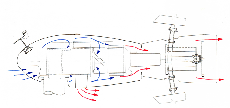
The nacelle is cooled entirely by the passing wind — no fans, pumps or liquid circuits. Ram air enters through intakes at the nose and hub gap (blue), washes over the gearbox casing and generator frame as it travels aft, and the heated air (red) exhausts through the tail cone and around the yaw column. Cooling capacity therefore rises naturally with windspeed, in step with the heat being generated: the harder the machine works, the harder the wind cools it.
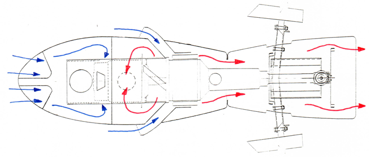
Revised cooling curves. Thermal testing confirmed the passive scheme with margin to spare. The revised flow pattern (Fig. 2) improved on the original estimate by capturing the recirculation cell that forms over the gearbox — mixing that raises local convective transfer and shifts the exhaust split toward the upper tail path.
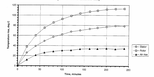
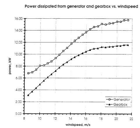
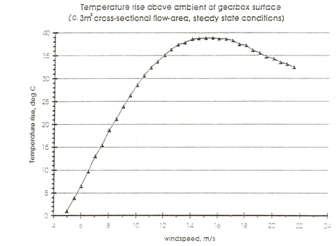
Fig. 3 shows the machine settling to thermal steady state in roughly three to four hours of continuous running: the rotor winding stabilises at about a 110 °C rise, the stator near 78 °C, while the cooling air itself picks up only ~33 °C — comfortably inside Class F insulation limits. Fig. 4 quantifies the duty: combined generator and gearbox losses climb to roughly 27 kW near rated windspeed, all of it rejected to the airstream.