The Components
The Carter 300 kW turbine is a lightweight, flexible system with a filament-wound spar that bends and twists to shed excess wind energy — two blades, a slender guyed tower, a compact downwind nacelle, and the winch that makes crane-free service possible.
 Composite Blades
The Blade
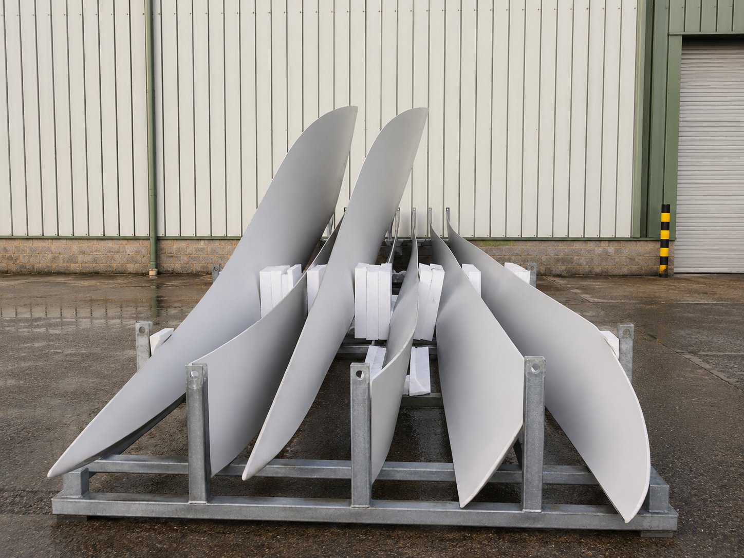
A teetering two-blade rotor built on the NASA LS-1 profile. The blades are deliberately flexible — they shed gust loads by bending rather than fighting them, cutting fatigue through the drivetrain and tower and allowing a far lighter machine.
- 2-Blade Teetering Rotor
- NASA LS-1 Profile
- Flexible / Load-Shedding
- Downwind
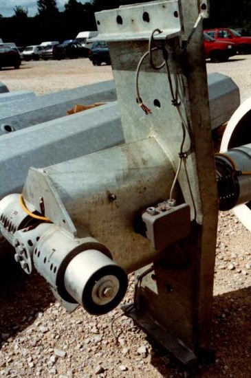 Teeter Hub
The blade hub is mounted on teeter bearings, which allow controlled movement of the rotor assembly. These bearings help absorb blade and hub vibrations, reducing the transmission of bending and torsional loads to the main drive shaft, gearbox, and tower structure. By accommodating dynamic rotor motions, the teeter system improves component life and enhances overall turbine reliability.
One of the most significant dynamic loading events occurs during sudden shutdowns, grid loss, emergency stops, or other operational interruptions. During these events, the tower can deflect into a pronounced “S-shape” as it absorbs and dissipates the rotor’s kinetic energy. This behaviour is a normal part of the turbine’s design and can appear quite dramatic to those unfamiliar with flexible wind turbine structures.
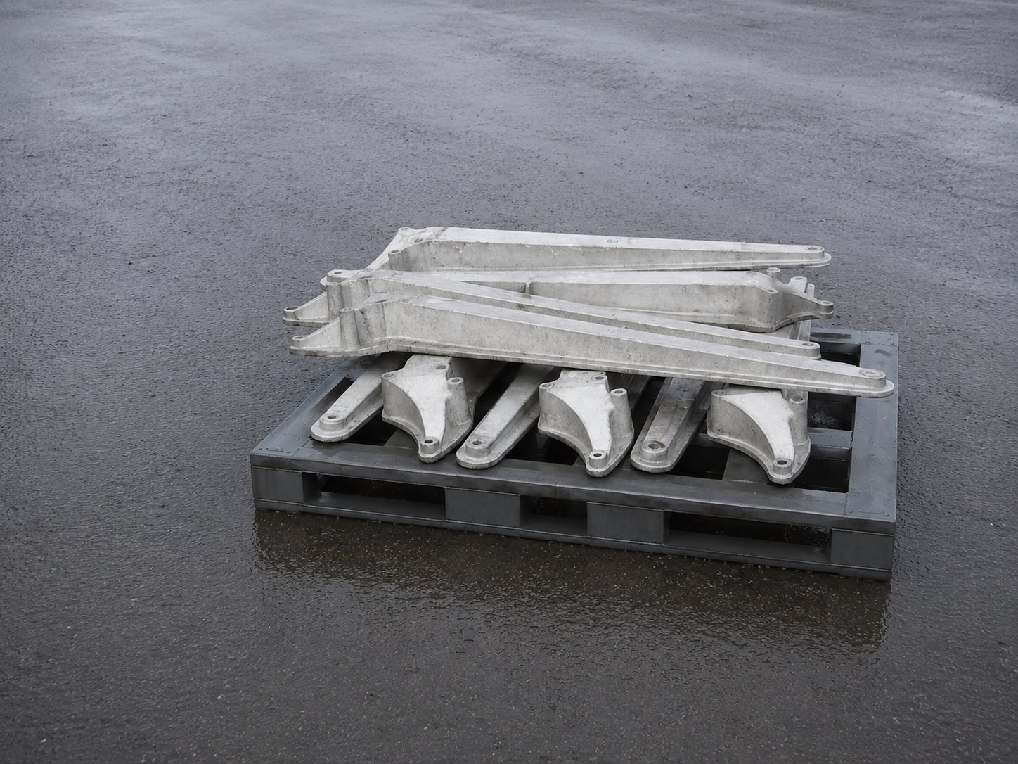 Counter Balance Arms
Blade Counter Balance Arms
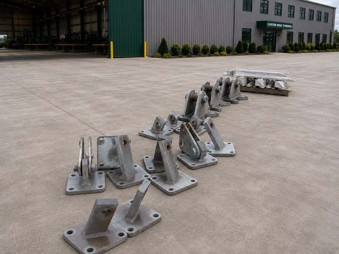
Cast counter-balance arms and root fittings that carry each blade at the teetering hub. Balancing the two-blade rotor keeps loads even through the drivetrain and tower, and the arms are produced as matched sets ready for assembly.
- Cast Alloy Arms
- Matched Sets
- Teetering-Hub Mount
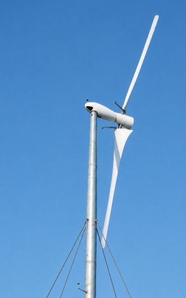
The counterbalance weights serve as an independent overspeed safety device. If the rotor speed increases beyond its design limit, the centrifugal forces acting on the weights at the ends of the arms increase proportionally. These forces generate a torsional moment on the blade assembly, causing the blades to automatically change pitch toward a stall position. As the blades stall into the feathered position, aerodynamic force is reduced, limiting rotor speed and slowing the turbine. Once the rotor speed has decreased to a safe level, the mechanical brake mounted on the drive shaft can be applied to bring the turbine to a controlled stop.
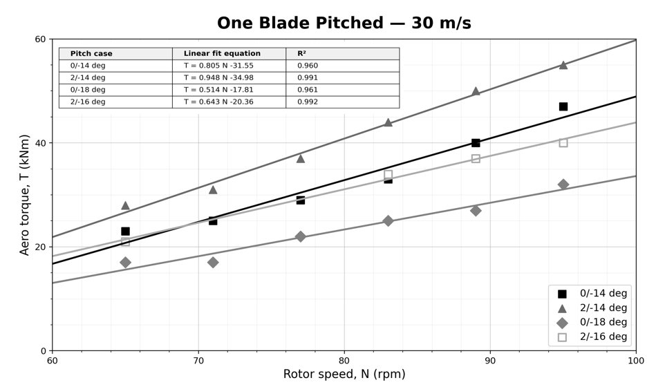
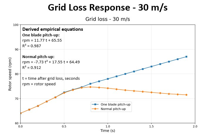
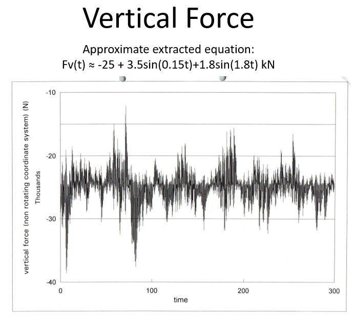
Typical fatigue and dynamic loading spectrum on blade and support assembly.
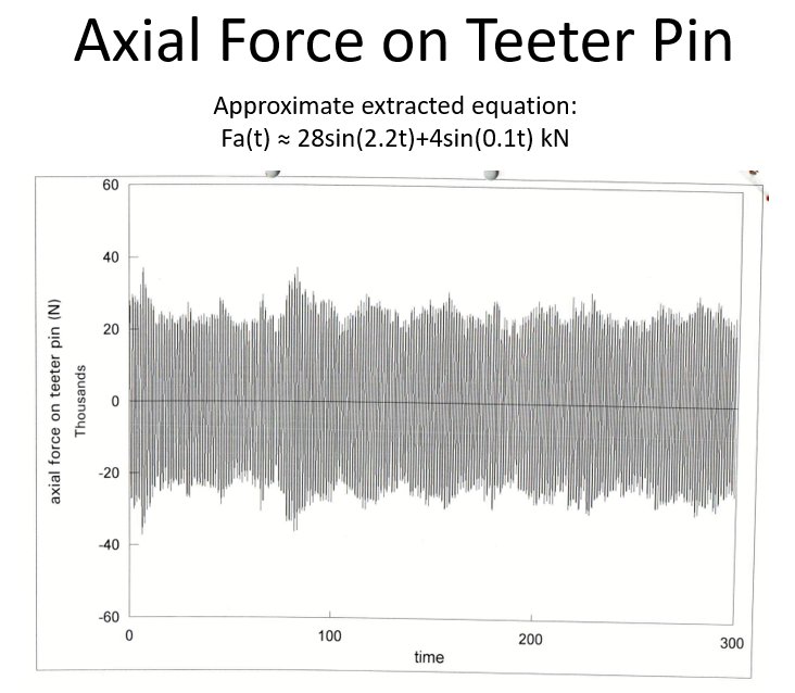
Typical fatigue and dynamic loading spectrum on blade and support assembly.
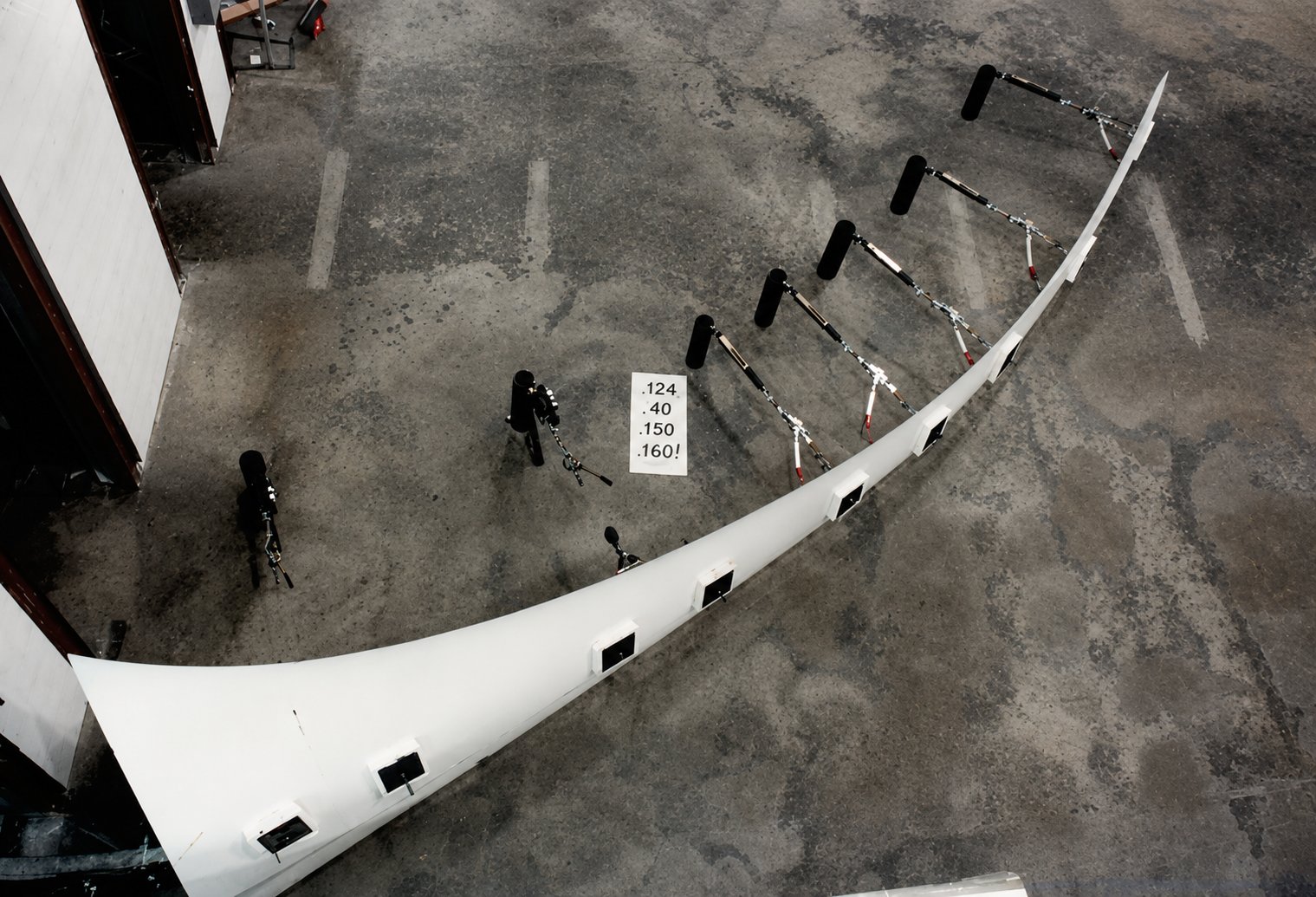 Structural Test
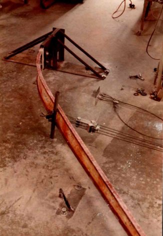 Structural Test
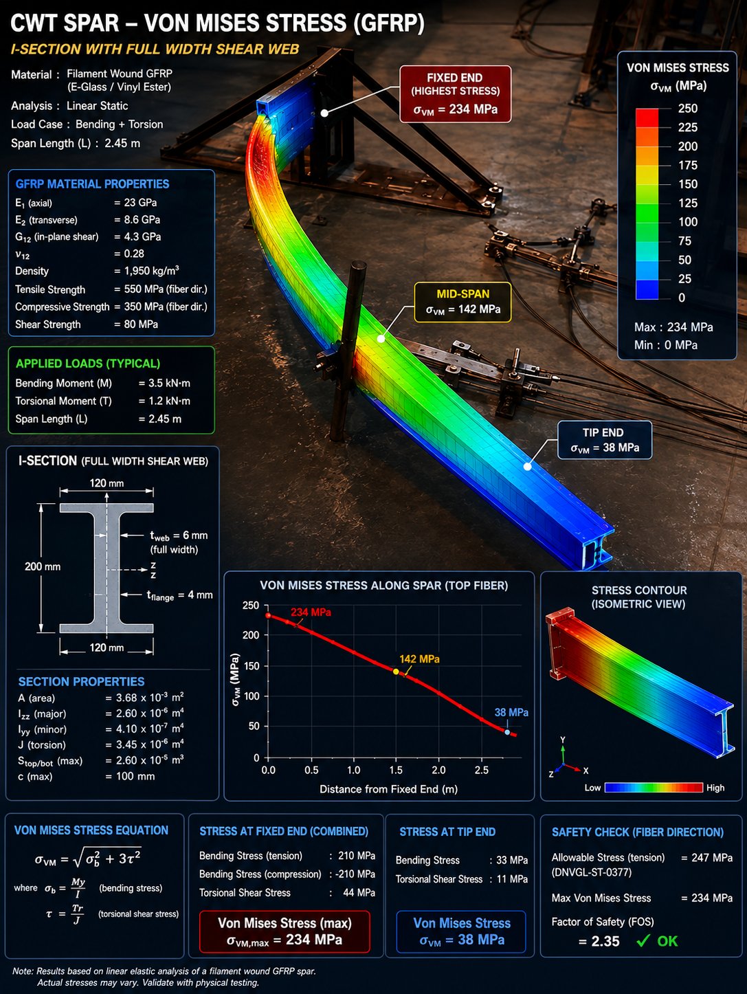 FEA — Von Mises
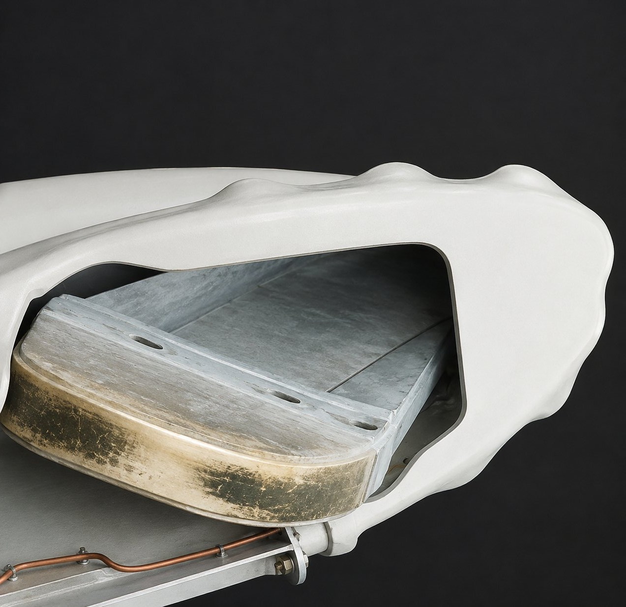 Spar Root
From the Blade Shop
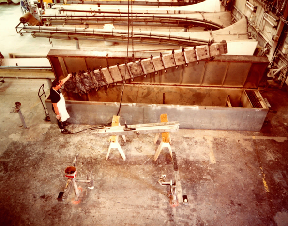
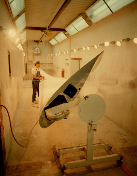
Period photographs from Carter blade production — spar protection and final finishing.
The Tower
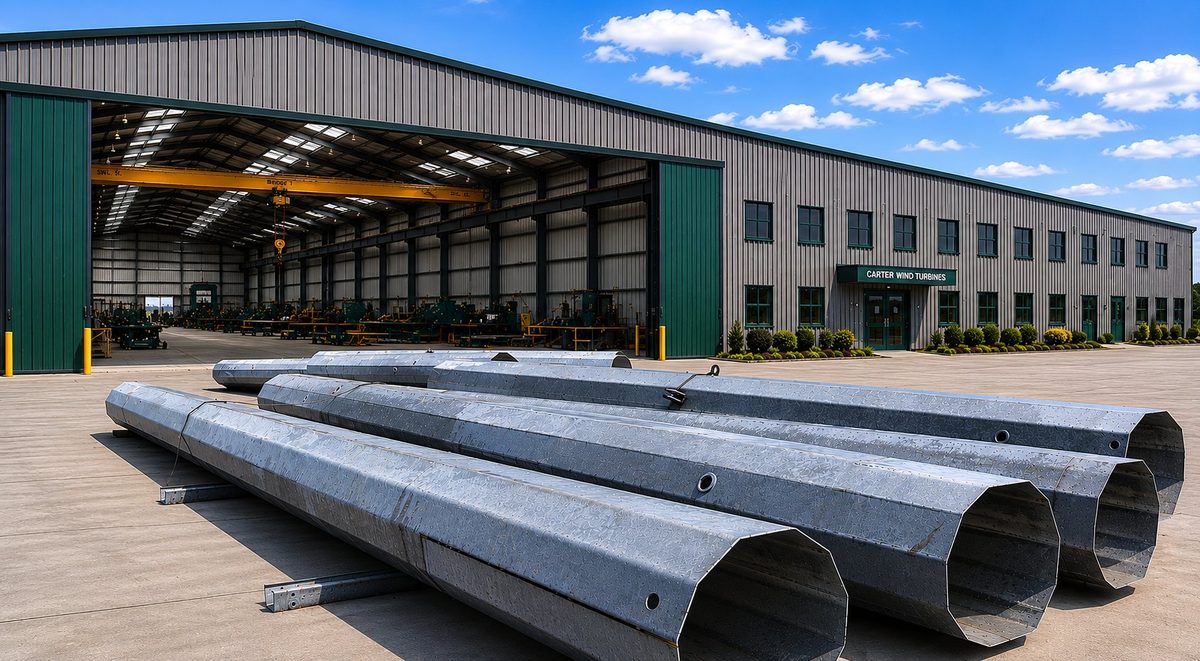
A slim steel tower held upright by guy cables rather than a heavy free-standing tube. It carries the rotor with a fraction of the steel and sits on a much smaller foundation — lowering cost, weight, and ground disturbance.
The tower is fabricated from rolled steel plate welded into tapered tubular sections that are assembled on-site. During installation, adjacent tower sections are joined by drawing them together with a hydraulic ram, creating a strong and reliable connection.
It is intentionally designed with controlled flexibility to absorb the kinetic energy generated during rapid turbine shutdowns. By flexing and twisting under load, the structure reduces peak stresses and helps protect both the turbine and tower components from shock loading.
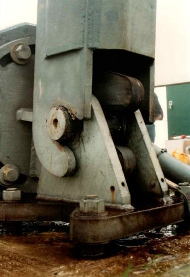
The tower base is mounted on a hinged foundation connection, allowing the structure to accommodate bending loads without transferring excessive moments into the foundation — improving structural efficiency and reducing foundation requirements.
All tower sections are sized to fit within a standard 40-foot shipping container, minimizing transportation costs and simplifying logistics for domestic and international deployment.
- Welded Tapered Sections
- Hydraulic-Ram Joints
- Controlled Flexibility
- Hinged Base
- Ships in 40′ Container
 Tower Base
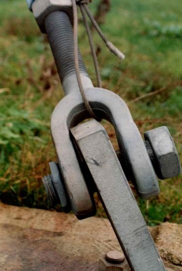 Guy Anchor
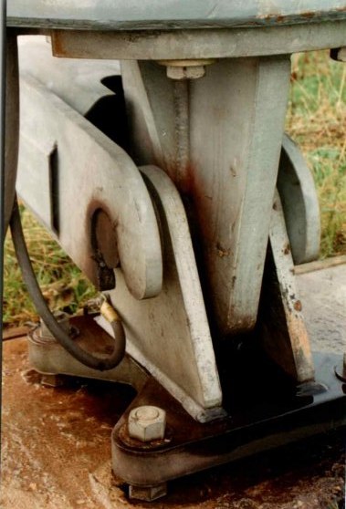 Tower Pivot
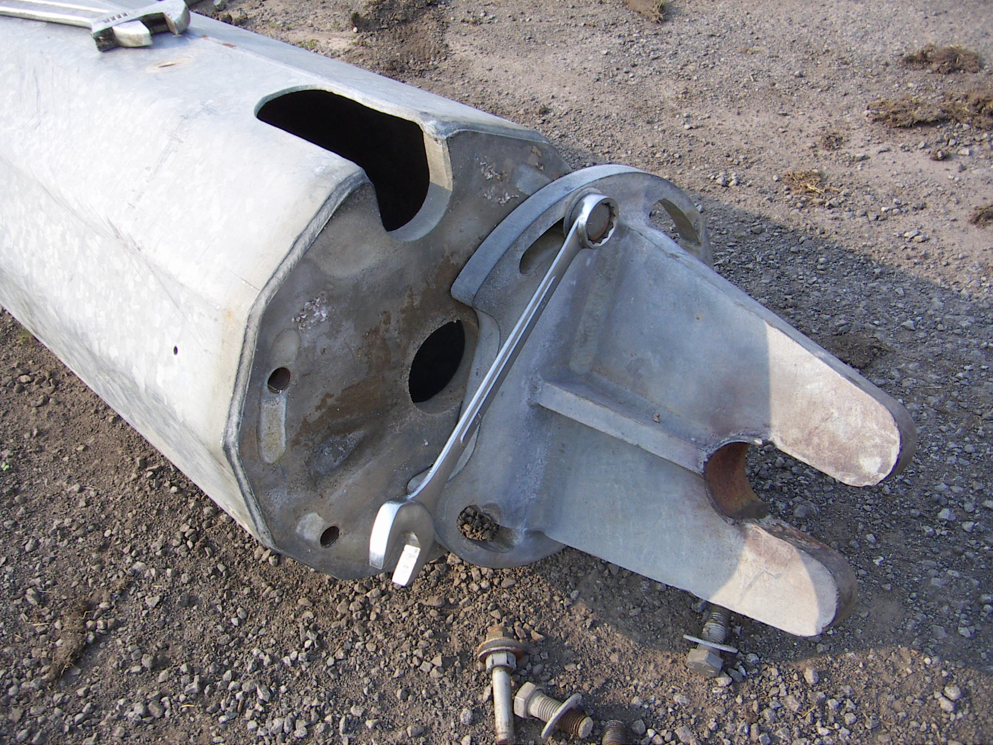
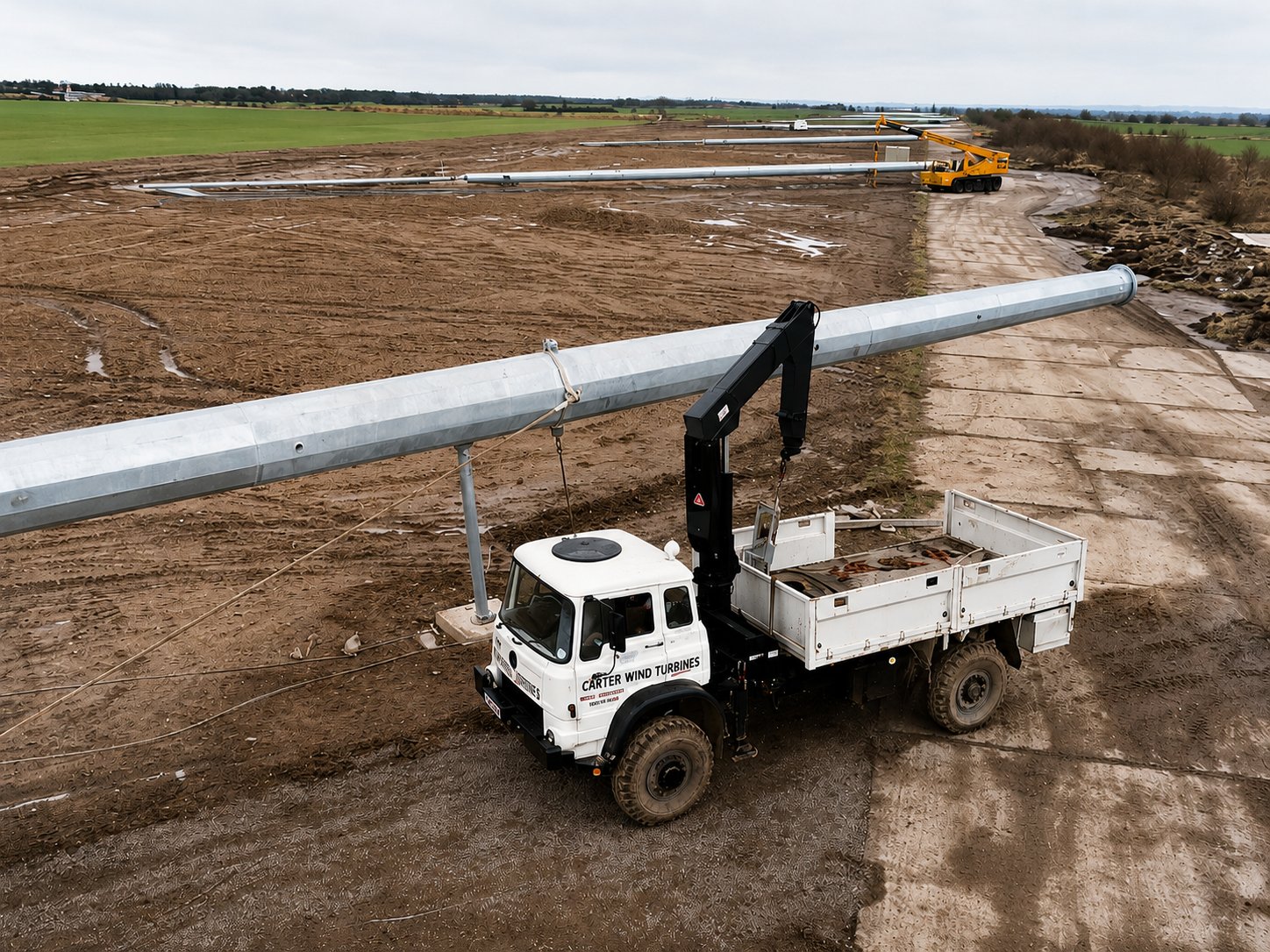 Site Construction
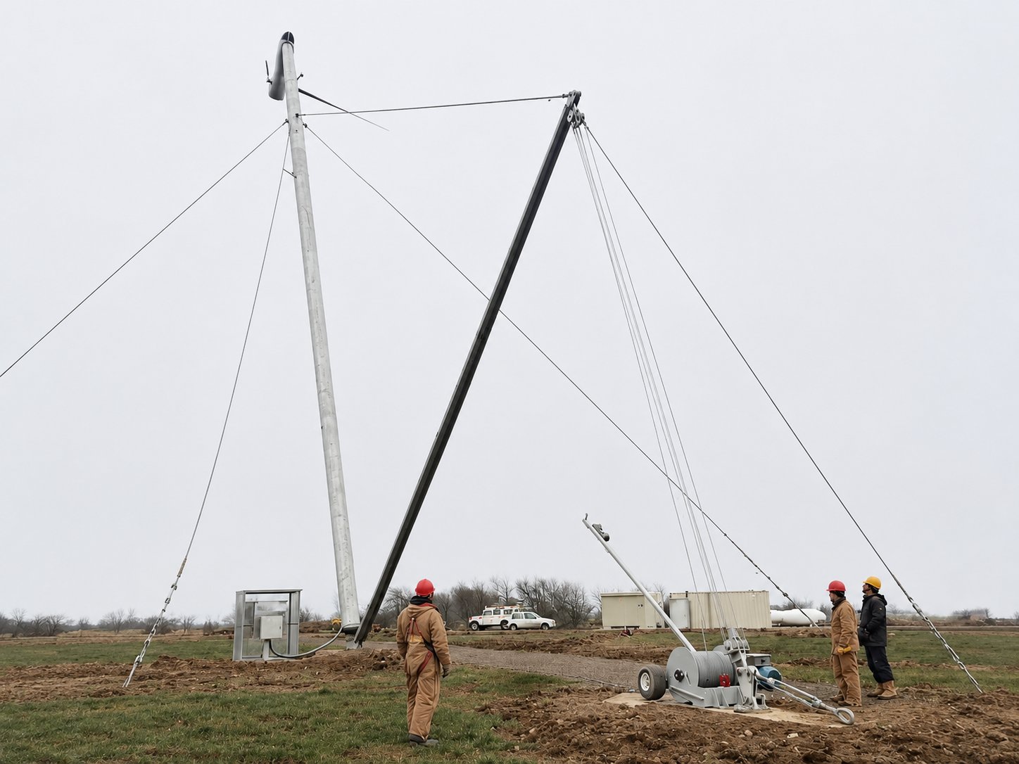 Tower Raising
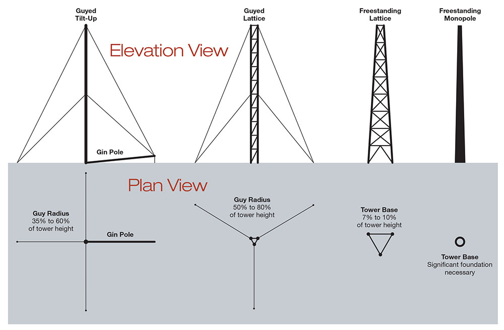 Tower Types
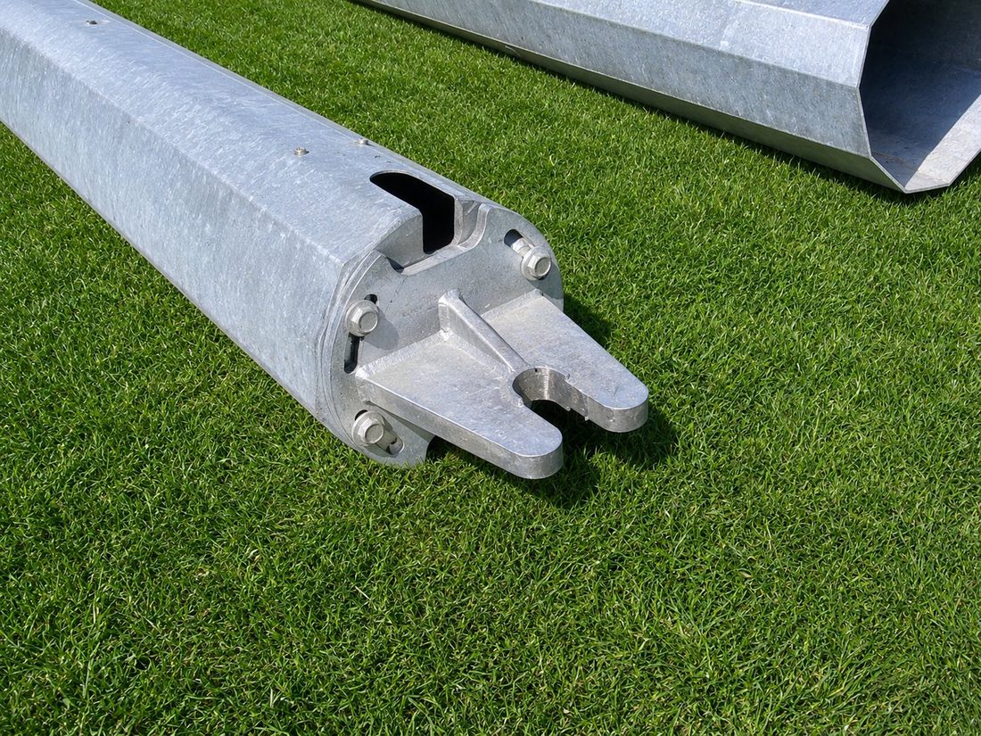
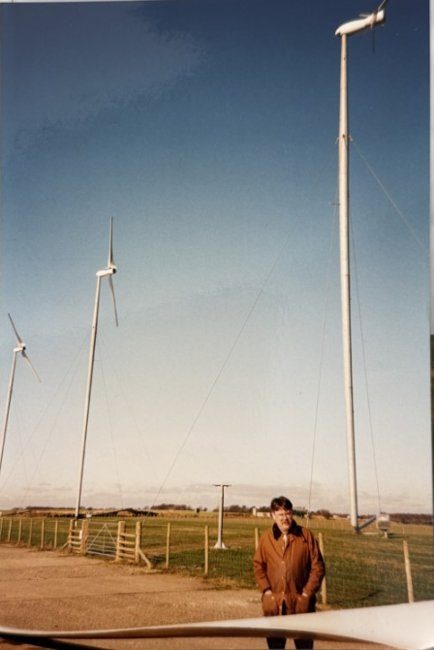
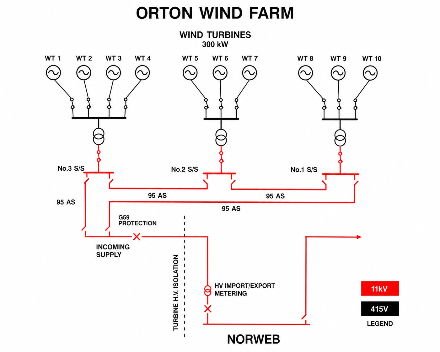
At our Orton Wind Farm Cumbria in the UK — note the tower rest stand.
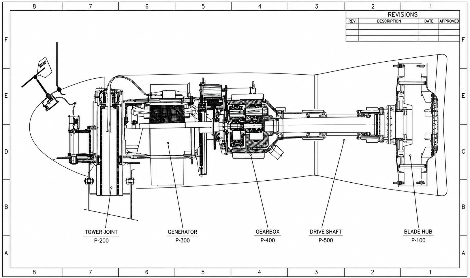 Assembly Drawing
The Generator
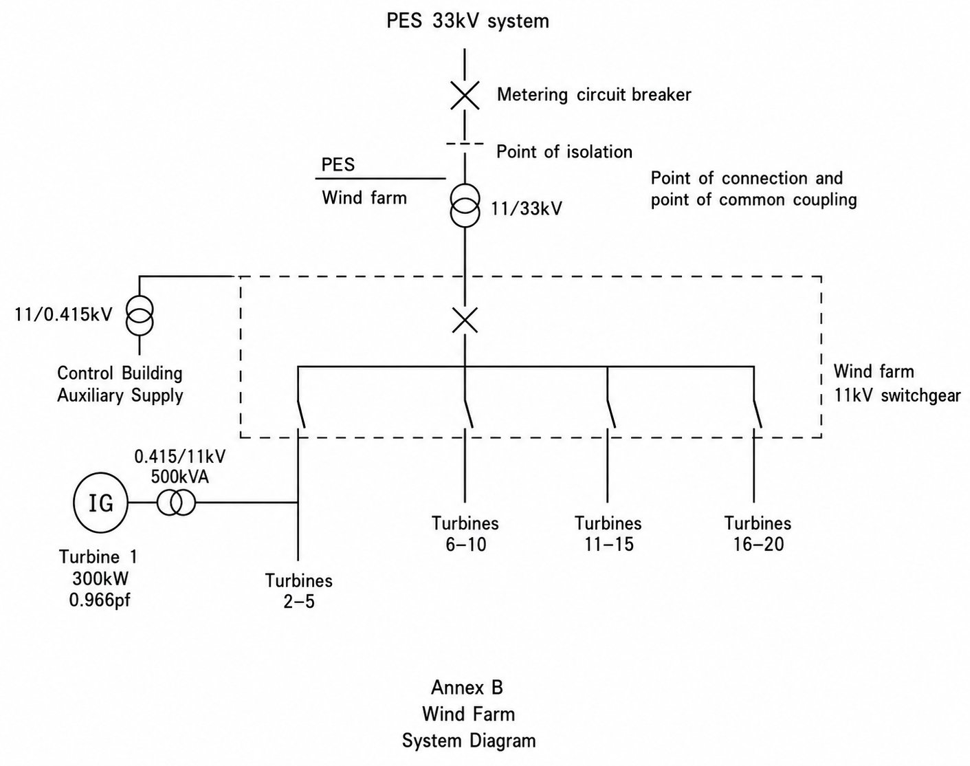
The generator converts the rotor’s mechanical power into electricity, sized to the machine’s 300 kW rating. Mounted in the downwind nacelle alongside the drivetrain, it is kept compact and serviceable so the whole power head can be brought to ground level for maintenance.
Direct coupling to the gearbox output keeps the assembly simple and reliable, and the unit is matched to the turbine controller for grid-synchronised output, instantaneous power measurement, and real-time fault and alarm monitoring.
- 300 kW Rated
- Grid-Synchronised
- Gearbox-Coupled
- Nacelle-Mounted
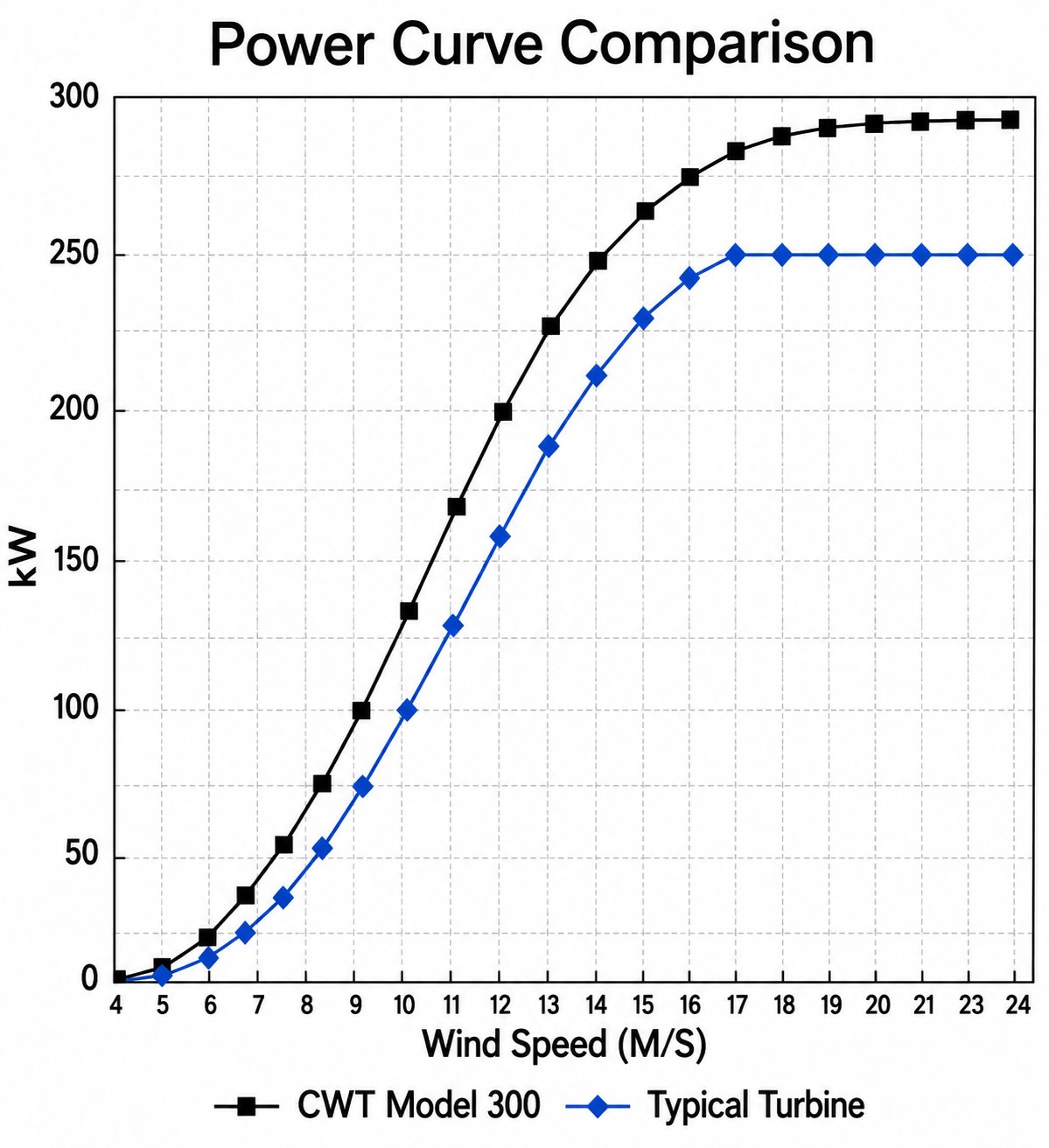 Power Curve
Annual Energy & Income
Enter your site’s mean wind speed and electricity price. The estimate applies the CWT Model 300 power curve across a Rayleigh wind-speed distribution (the IEC standard derived from the mean) to predict yearly output and revenue for one turbine.
Estimate for a single CWT Model 300 turbine using a Rayleigh wind distribution and a typical 95% availability. Actual output depends on site turbulence, air density, wake losses, and grid availability. Indicative only — not a performance guarantee.
Power & Energy Estimator
Adjust the inputs to see the wind-energy equations recalculate live. Defaults are example values for a Carter-class 300 kW machine — enter your own site figures to model your installation.
Design Inputs
Power Curve — Output vs Wind Speed
Generator Build — Workshop
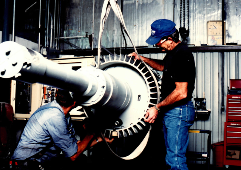
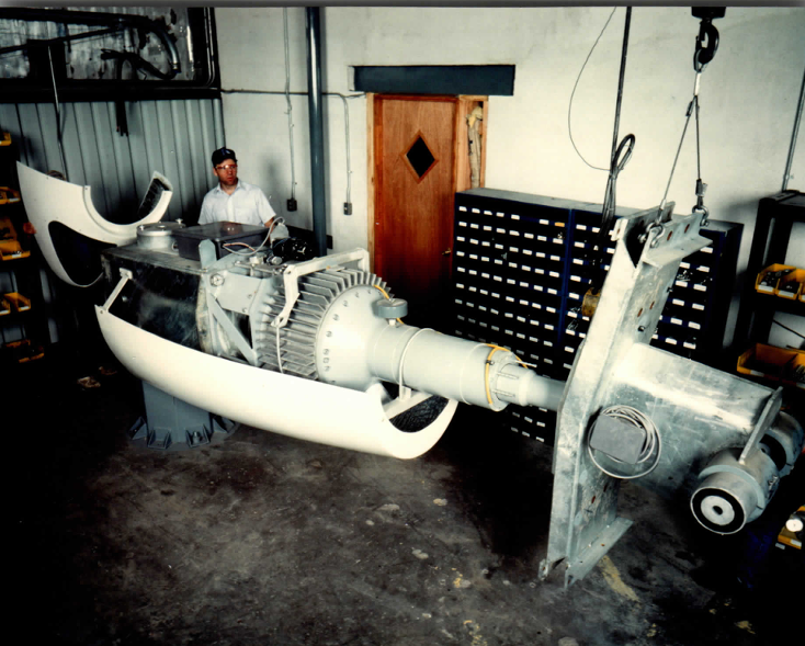
Period photographs from generator and drivetrain assembly.
 Carter Wind Turbines · UK
The Nacelle
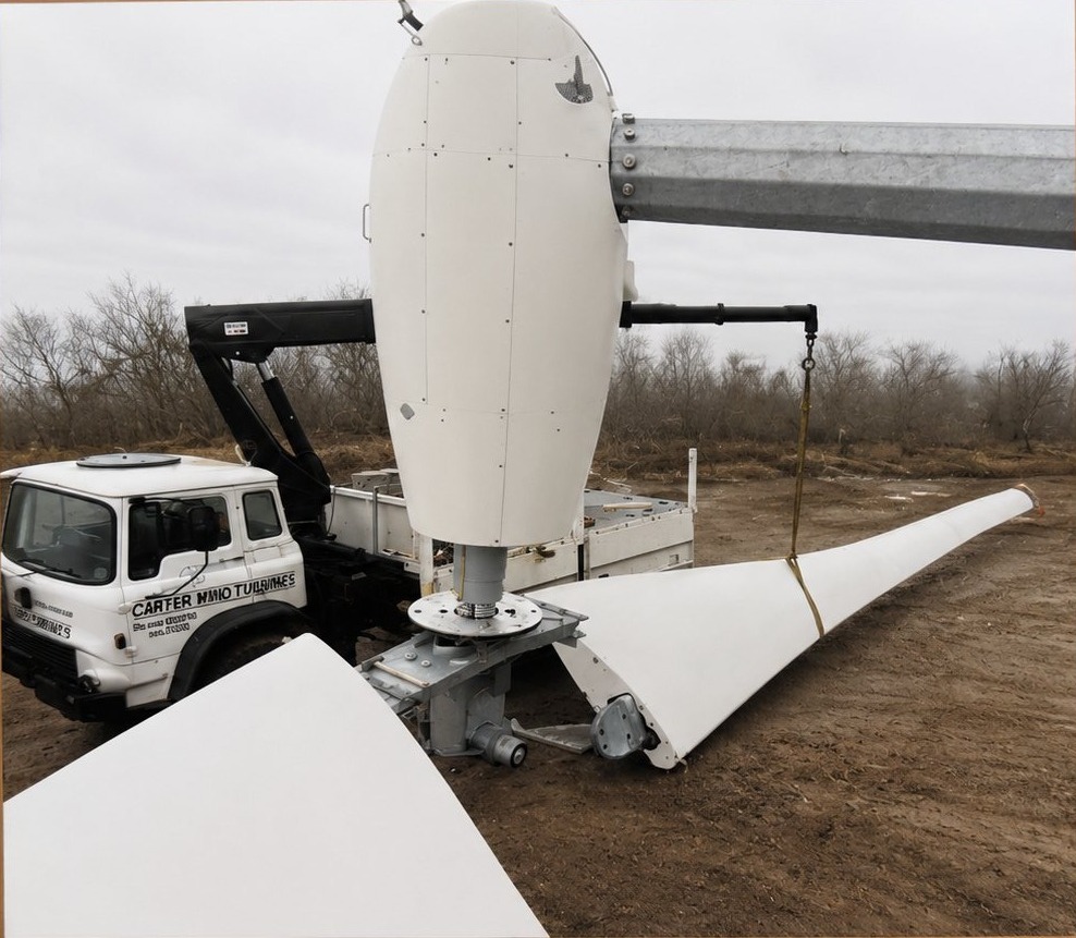
The compact nacelle houses the generator and drivetrain and sits downwind of the tower, so the rotor naturally tracks the wind with minimal yaw machinery. Kept light and simple, it is the part that comes to ground level for service.
Built and tested at our own workshop, each nacelle assembly is delivered ready to lift straight onto the tower pintle — here, a batch of completed units stands palletised outside the factory ahead of dispatch.
- 300 kW Rated
- Downwind Yaw
- Compact Drivetrain
- Low Mass
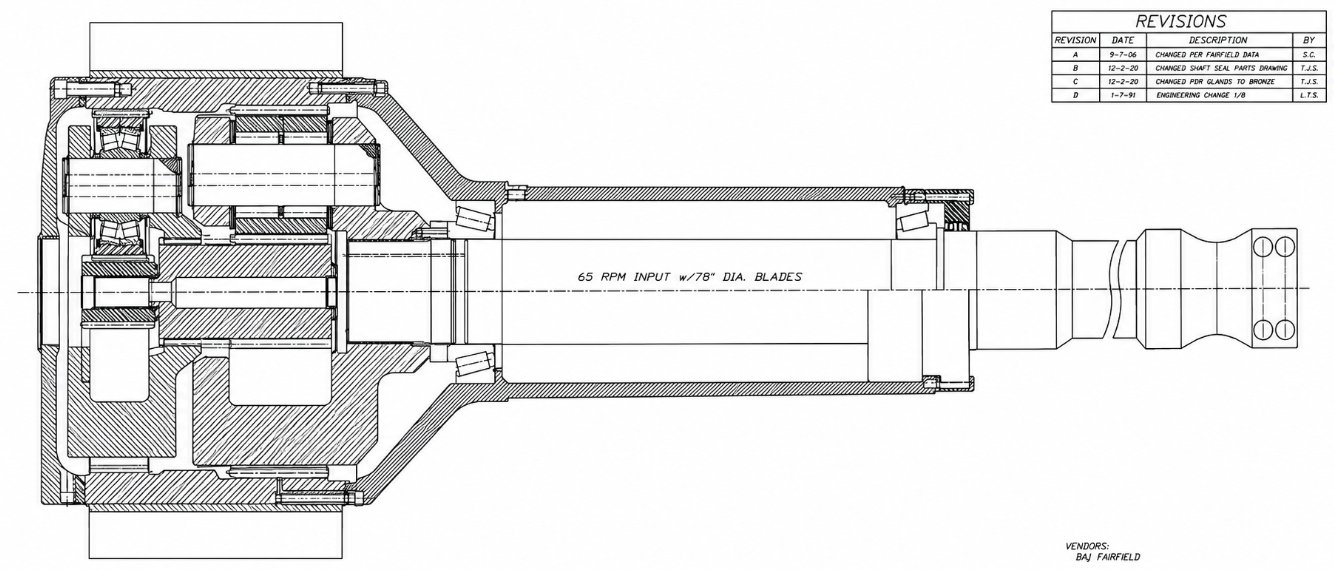 Drivetrain
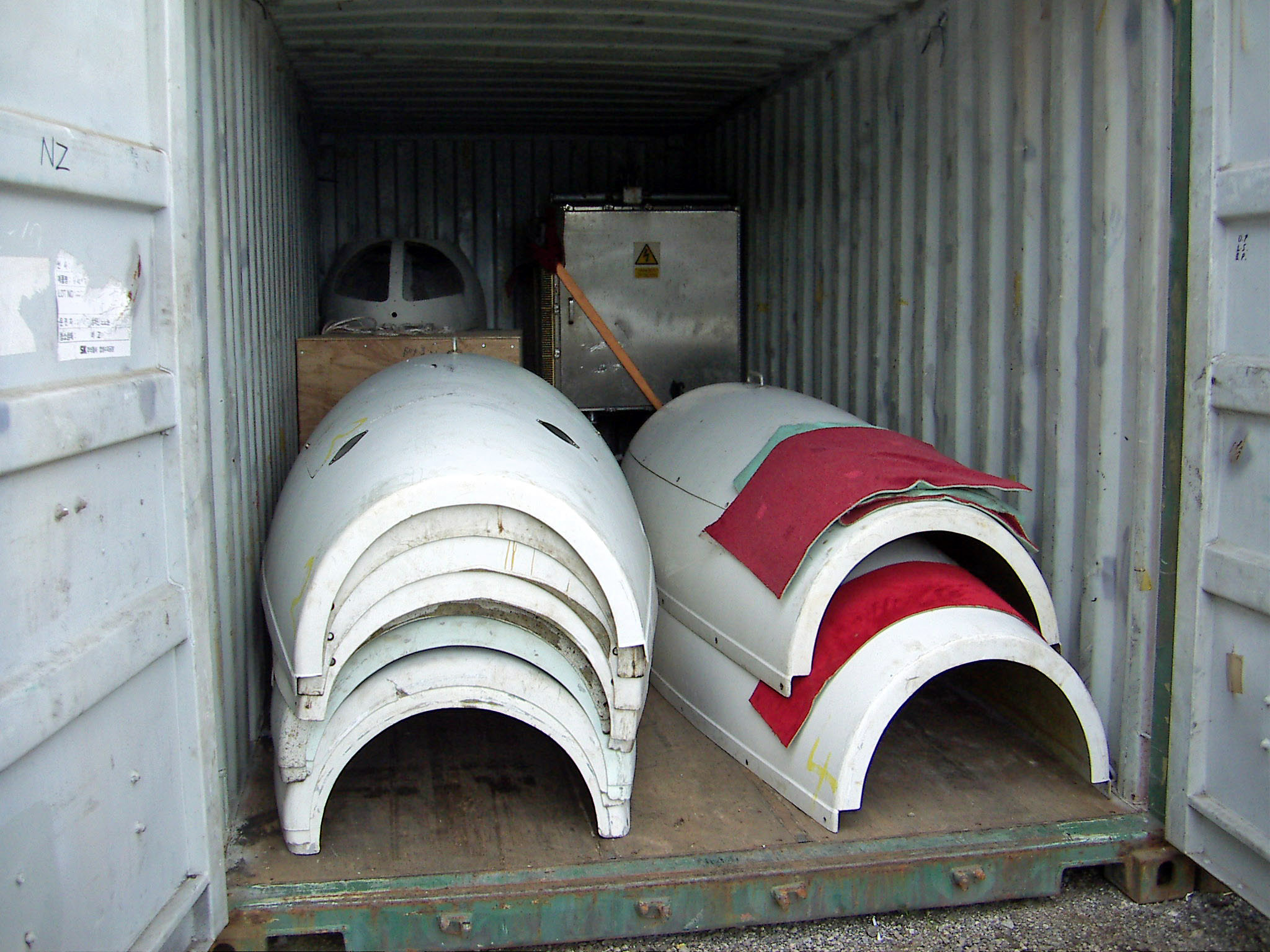 In Transit
Nacelle Covers On Shipment
The lightweight composite nacelle covers nest together for efficient transport. Here a set is packed into a standard shipping container ahead of export — part of a consignment bound for New Zealand.
- Nested Composite Covers
- Container-Packed
- Export Ready
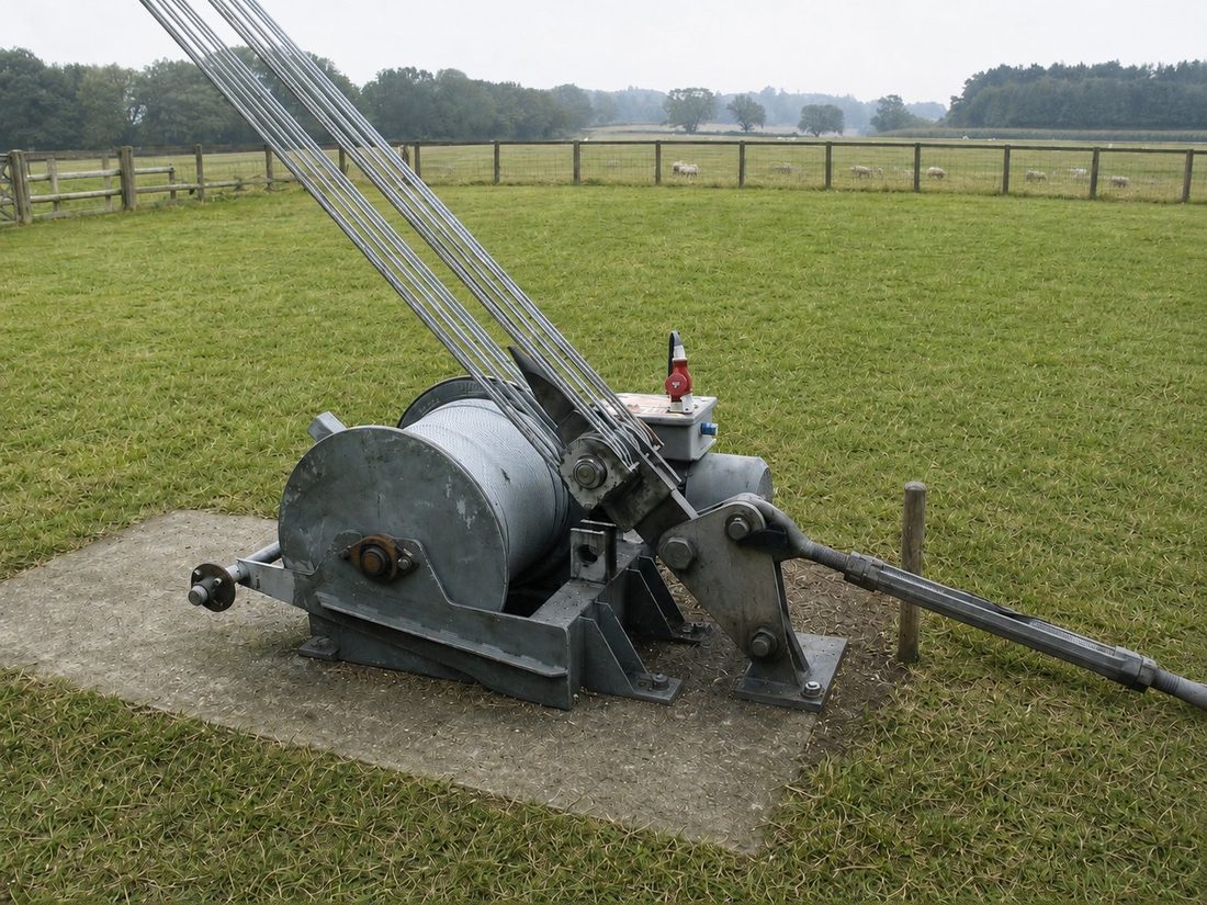
Winch and Winch Pad
A ground-level winch lowers and raises the entire hinged tower under controlled tension — no crane and no tower climbing, which makes the Carter machine ideal for remote sites and dramatically cheaper to install and maintain.
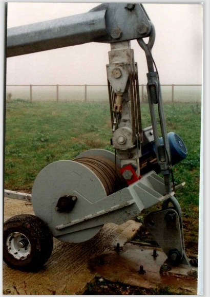
The turbine is equipped with a winch and a reinforced concrete winch pad. The winch is movable, allowing a single winch to be shared among multiple turbines within a small wind farm.
This approach reduces installation and maintenance costs while providing flexibility for turbine erection, lowering, inspection, and servicing operations. The winch pad provides a stable, durable foundation for safe operation under all weather conditions.
- Controlled Tilt-Down
- No Crane Needed
- Ground-Level Service
- Single-Visit Maintenance
 Great Orton, Cumbria
A Purpose-Built Turbine Controller
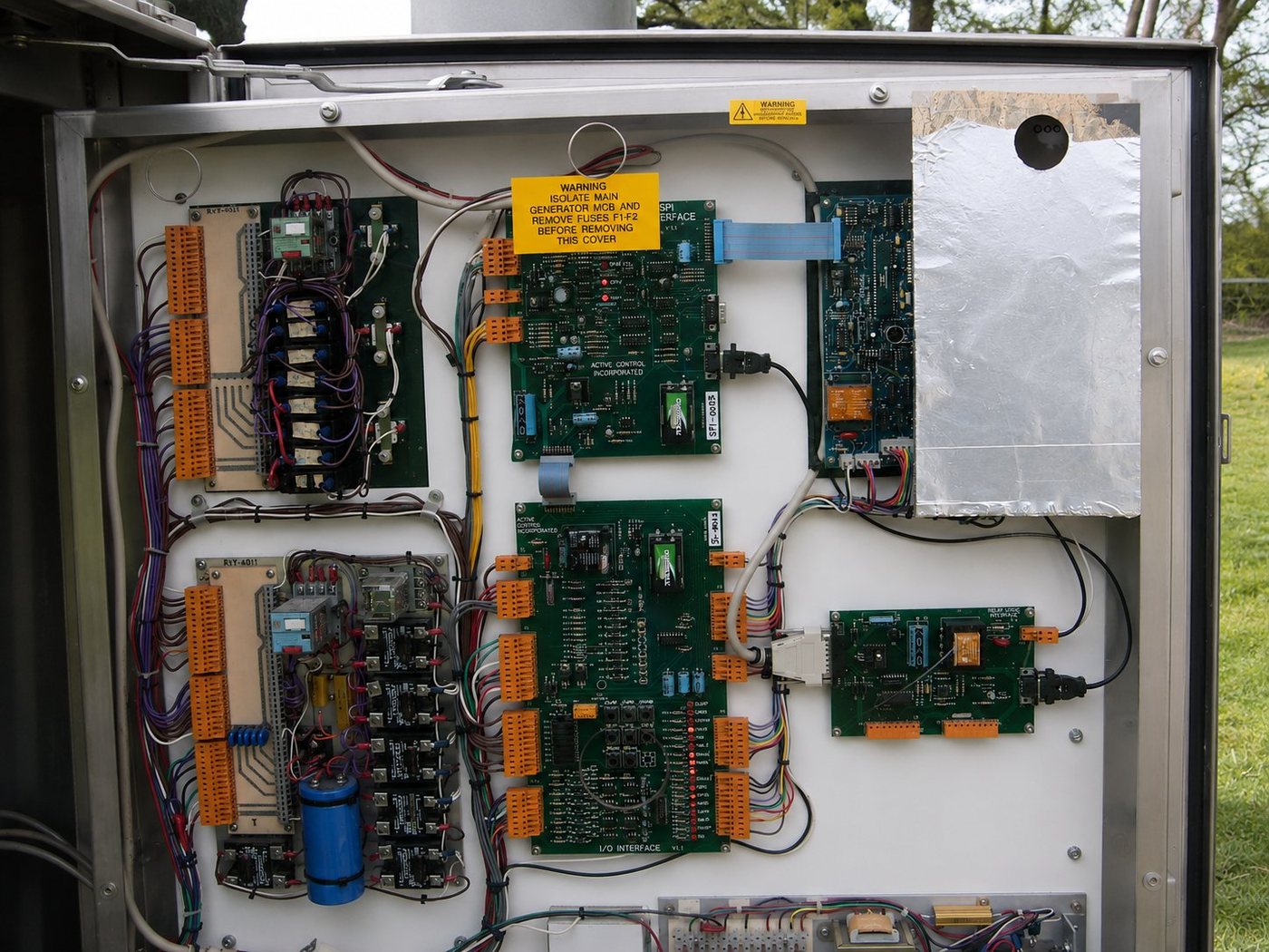
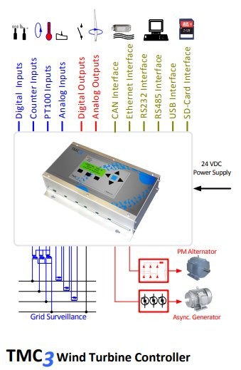
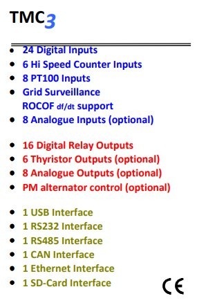
The controller monitors the live operation of the turbine and all associated assemblies and reports operational data remotely to the operations center via a cellular link. Operations personnel can monitor and control each turbine day to day and measure power output instantaneously, with alarms, faults, and warnings detected and communicated in real time.
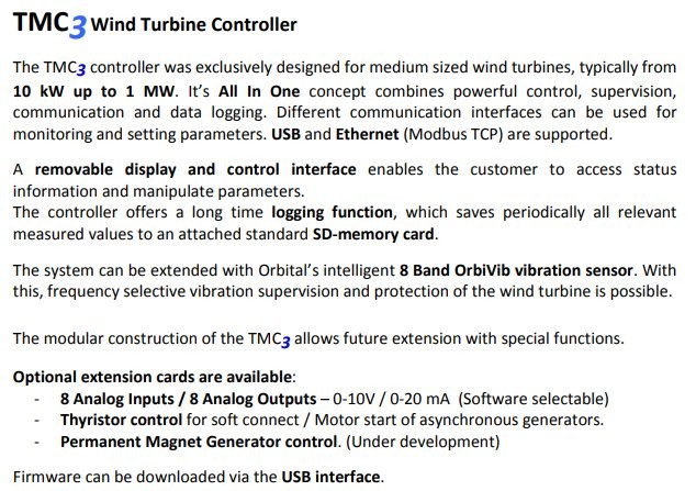
Recognizing the need for improved safety, reliability, and operational efficiency, Steve entered into a joint venture with Orbital Sciences of Denmark to develop a new turbine controller.
The controller was designed in-house and jointly developed with Jens and the engineering team at Orbital Sciences. Following development and testing, the controller was manufactured by Orbital for deployment across the Carter Wind Turbines fleet.
The new system incorporated the latest electronic interfaces, enhanced sensor technology, and improved communications capabilities. These advancements provided greater operational awareness, increased reliability, more accurate performance monitoring, and enhanced safety throughout turbine operation.
- Live Remote Monitoring
- Cellular Link
- Instant Power Readout
- Real-Time Alarms & Faults